PillStim
The design, development, and characterisation of a single-channel electrical stimulator for use in a single-use ingestible pill.
| Mechanical | 26 mm (L) × 11 mm (D) — PillCam dimensions |
| Electrode surface area | 190 mm² — dome electrodes on ends of pill |
| Battery capacity | 445 mWh/cm³ — silver oxide |
| Battery life | 5 days |
| Stimulation type | Biphasic |
| Stimulation frequency | 1 – 10 Hz |
| Stimulation amplitude | 10 – 5000 µA |
| Stimulation pulse width | 100 – 500 ms |
| Stimulation compliance | 14 V |
| Charge max per phase | 500 µC |
| Charge balance | < 100 nC net charge |
| Stimulation protocol | To be advised |
Tissue Safety
Safe limit is 57 µC/phase (190 mm², 30 µC/cm²). Post-stimulation shorting handles residual charge; a DC blocking cap is optional but costs compliance headroom. A centre ring electrode enables per-hemisphere impedance checks — this may be essential since partial tissue contact reduces safe thresholds significantly.
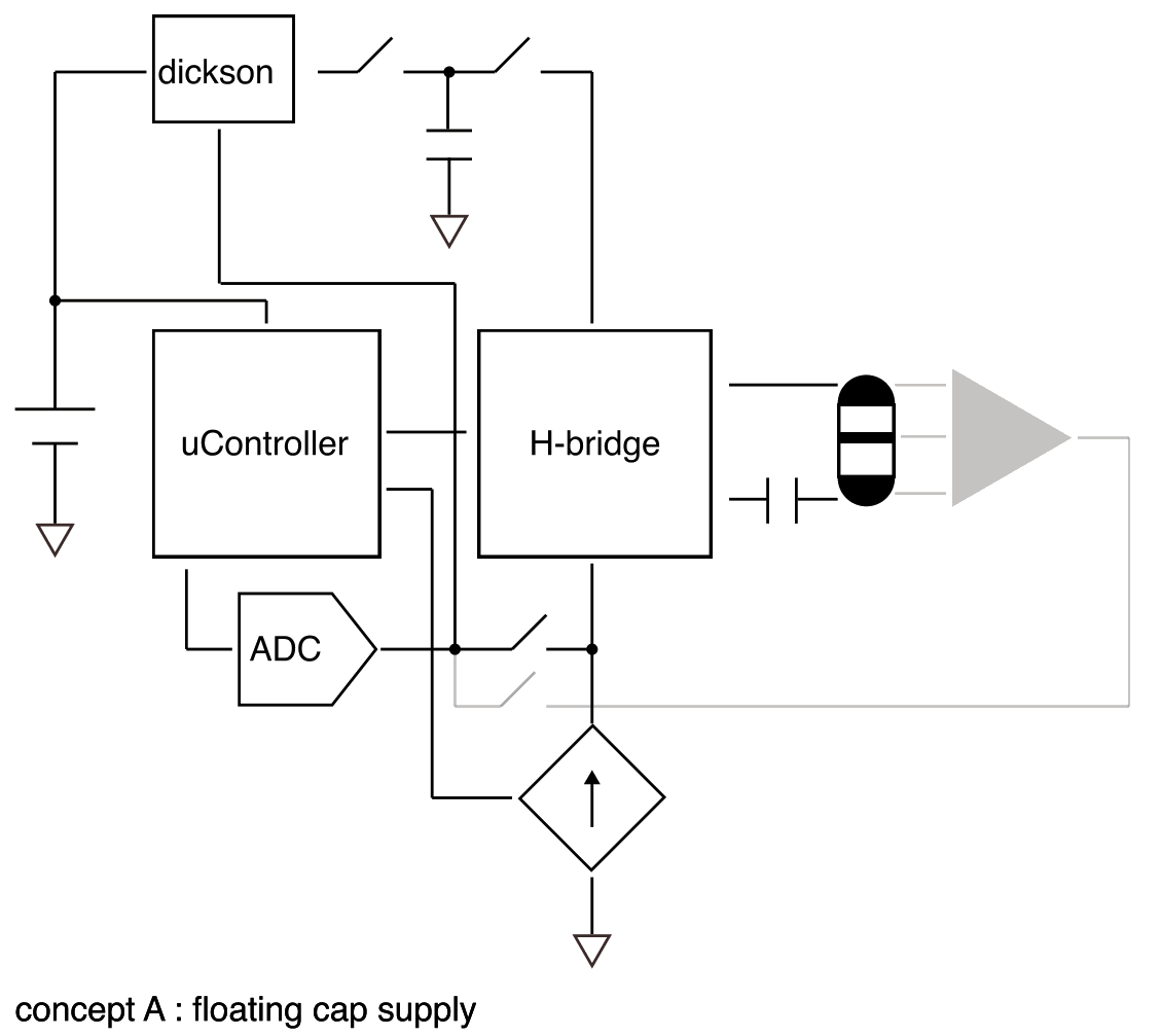
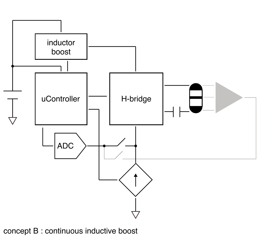
Efficiency
Tissue stimulation should dominate power consumption. Since current is fixed, power drawn is 14 V × Istim, but power delivered to tissue is only Vt × Istim. Dynamically setting compliance voltage based on measured electrode impedance before each pulse minimises this overhead.
Device Safety
Redundant safety mechanisms — DC blocking capacitor and hardware charge limiting — prevent adverse effects in the event of malfunction.
-
01Low-Resolution SimulationIdeal simulations confirming the fundamentals of the proposed architectures and ideal component values. Includes power consumption, efficiency, charge balance, and verification of stimulation compliance.
-
02Component SelectionBased on simulation results and requirements, components and values will be selected and prepared for detailed simulation.
-
03High-Resolution SimulationExact component models integrated and circuits characterised to verify all requirements are met.
-
04LayoutDesigns transferred to contractor for PCB layout and fabrication.
-
05FirmwareFirmware written and tested using a development board. Additional test code written to validate hardware functionality.
-
06Bench TestingFabricated boards fully characterised and validated against requirements.
-
07ReportPreliminary report created for client review.
| Primary contact |
Kyle Slater k@musicdust.com +61 415 141 297 |
| Company details |
Music Dust Pty Ltd ABN 33 659 694 818 BSB 083-004 · ACC 511469302 |